In this blogpost @astralvx will describe the physical hardware attack to capture a Bitlocker key in transit across the SPI bus. All information here is in the public domain in one form or another and not proprietary. We shall discuss the details of Bitlocker, boot flow from pre-boot to OS, an introduction to TPM 2.0 and SPI bus, soldering onto the legs, logic analyzers, how to analyze the SPI stream, using the extracted VMK to decrypt a Bitlocker protected volume, and lastly some mitigations.
Introduction to Bitlocker
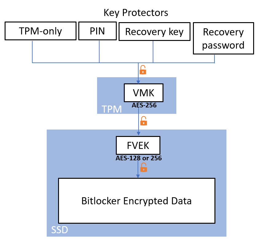
Bitlocker is Microsoft’s full volume encryption, note it is not full disk encryption. Data on a volume (e.g. C:\) will be encrypted with the Full Volume Encryption Key (FVEK), and the FVEK is stored in metadata of a disk volume. The FVEK itself is encrypted with the Volume Master Key (VMK), and this VMK is stored in the TPM. Key Protectors (KP) can be used used to unseal the VMK from the TPM. More details in the Bitlocker FIPS 140-2 document [1].
Boot Flow
Condensed list. There is significant amount more regarding ACM, DRTM, etc in the initial steps which will be skipped over since the focus is on the TPM.
- Root of Trust – chain of trust proceeding is anchored here, for OEM vendors this will be the Embedded Controller (EC) and it’s integrity checks of Initial Boot Blocks for EFI
- Measured Boot – UEFI BIOS loads and performs cryptographic hashing of EFI components (executable firmware), and extends (appends) hashes into TPM PCR banks.
- Boot manager (bootmgfw.efi – containing initial Bitlocker code) on unencrypted SYSTEM partition started
- Boot manager reads NVRAM variable to find OS bootloader path (e.g. C:\windows\system32\winload.efi)
- Boot manager asks TPM to unseal the VMK.
TPM analyzes the chain of trust by checking PCR registers after ‘Measured Boot’ in step 2, it releases VMK if they are the expected values.
Thus any modification to firmware will break this chain of trust, stop execution, and prompt the Bitlocker recovery screen - Boot manager with VMK decrypts the FVEK to decrypt the entire OS volume (C:\)
- Boot manager then verifies integrity of the bootloader (winload.efi) and executes it
- Bootloader loads NT Kernel (ntoskrnl.exe) into memory
- Bootloader loads into memory: HAL, SYSTEM registry hive (%SystemRoot%\System32\config\SYSTEM), SERVICE_BOOT_START drivers
- Bootloader then executes the NT Kernel (ntoskrnl.exe)
- Bootloader lastly calls ExitBootServices(), and memory used during EFI boot phases is reclaimed, thus ending the boot phases and the OS Kernel starts
Introduction to the TPM
The Trusted Platform Module (TPM) is a cryptoprocessor. It holds cryptographic keys, in persistent memory such as VMK, Endorsement Key (EK), Storage Root Key (SRK), and in volatile memory such as PCR, AIK, SK.
TPM types:
- Discrete TPM – dedicated chip, Infineon, Nuvoton, STMicroelectronics, etc
- Integrated TPM – part of another chip, all Intel chips that support TXT
- Firmware TPM – AMD Platform Security Processor (PSP) has TPM 2.0 (fTPM), Intel Platform Trust Technology (PTT), Qualcomm fTPM
- Hypervisor TPM – rely on hypervisor for isolated execution environment, hidden from VMs
- Software TPM – emulation of TPMs through OS software, least secure
When Bitlocker is enabled PCR 7 and 11 are used for Secure Boot integrity validation.
CPU communicates with TPM through PCH, on modern system typically over the SPI bus.
Introduction to the SPI bus
Serial Peripheral Interface (SPI) is a communication protocol
OEM vendors typically have a shared SPI bus for public SPI chip and TPM
The SPI bus specifies four logic signals:
- SCLK: Serial Clock (output from master)
- MOSI: Master Out Slave In (data output from master)
- MISO: Master In Slave Out (data output from slave)
- CS/SS: Chip/Slave Select (active low, output from master to indicate that data is being sent)
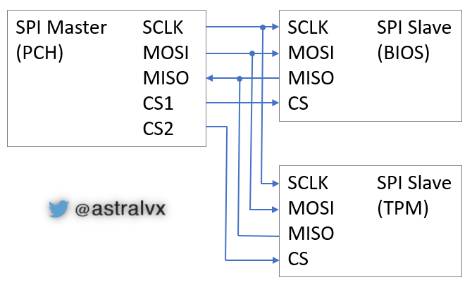
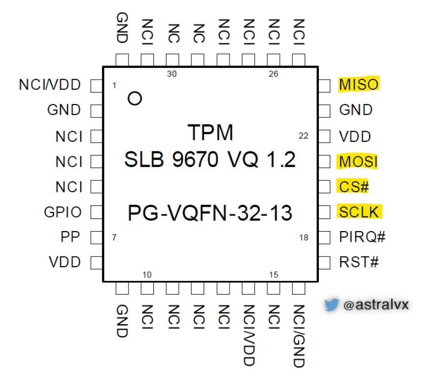
Since the SPI bus is shared as seen in Fig 3, data sent from the TPM to the CPU can be seen by other SPI devices. A typical PG-VQFN-32-13 package TPM has very fine legs (0.5mm spacing) and is difficult to solder onto, however the public SPI chip is more accessible for soldering as seen in Fig 4.
Soldering
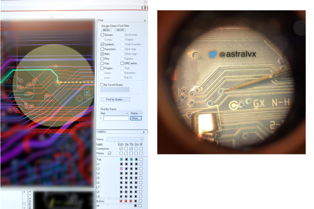
The leg width of the TPM seen in Fig 2, is 0.5mm it is difficult to solder debug probes on, unless you have a microscope and a steady hand. The public SPI chip with the BIOS is typically easily to attach to since it’s on a SOIC-8 package. If one searches online for manufacturer board datasheets one can find precisely where to solder a fly lead to a signal of interest when it exposes itself on the top layer. Modern notebooks typically have 10-layer PCBs (making it extremely tedious to solder) with vias (holes that provide electrical access from one layer to another) as seen in Fig 4, where different layers transport different signals e.g. PCIe (M.2, WWAN, PCI, etc), SPI, I2C, RF, NFC, audio, EMMC, HDMI, sensors, memory bus, USB, PD, and more.
Logic analyzer
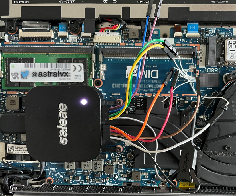
Once debug wires are soldered on, the Saleae Logic Analyzer can be attached to SPI_CLK, SPI_CS, SPI_SO, SPI_SI as seen in Fig 5. One should expect to encounter potentially erroneous data when reading due to signal integrity issues – from imperfect soldering resulting in cross talk amongst channels, or from debug cables being too long (thus adding more copper/resistance) causing impedance, and so on.
SPI stream
Once the logic analyzer is hooked up, change sampling rate to over 4x the TPM SPI clock speed. This oversampling is done to maintain nominal bandwidth otherwise aliasing will occur resulting in incorrectly sampled bytes. The Infineon Xenon TPM in Fig 2 runs at 3.3V and a maximum SPI clock speed of 43 MHz, therefore we need to sample at 43*4=172 MS/s (Millions Samples per Second), or 250 MS/s as provided by the fixed sampling rates of the Saleae Logic Analyzer.
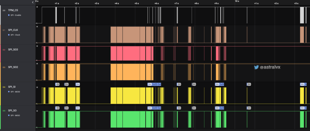
As you then power up a notebook and it goes through the boot phases, refer back to the ‘boot flow’ section. The Boot Manager (bootmgfw.efi) in pre-boot UEFI asks the TPM to unseal the VMK. If the PCRs are in the correct state and protectors validated, the VMK will be unsealed and sent across the SPI bus from the TPM to the Platform Control Hub (PCH) AKA chipset. This will result in a capture SPI stream as seen in Fig 6 and somewhere in there will be the 32-byte VMK.
Zooming into a single SPI transaction as seen in Fig 7. Specifically the TPM is returning the byte 0xC1. Notice TPM_CS is asserted hence it is the active slave device on the shared SPI bus. In this transaction there are total 40 cycles == 40 bits == 5 bytes, and it is as follows:
- 4 bytes are sent from PCH to TPM over MOSI as the request 80h D4h 00h 24h, and the TPM responds on MISO with C1h. Reading the TCG spec allows you to understand the command format.
- 0x80 = Read (MSB set), bits 5:0 are following data size, and 0 = 1 byte transaction.
- 0xD40024 = TPM_DATA_FIFO_0. On MOSI line (Master Out/CPU sending command data to TPM). 0x0024 = TPM Register for the FIFO data buffer between host and TPM, for commands or responses. Bitlocker only uses Locality 0, hence 0024. Locality 1 uses 1024, Locality 2 uses 2024 etc.
- 0xC1 (1 byte response) = MISO (Master In/CPU receiving response data from TPM)
This done 32 times will result in 32 bytes sent from the TPM to the PCH, hence the AES-256 VMK. However in our current scenario we will have hundreds of thousands of bytes captured in the SPI stream, so you will then need to dissect and obtain those 32 bytes.

Brute forcing
Once you have reliably captured the stream, one can brute force every 32-byte combination in the hundreds of thousands of SPI bytes to find the key.
Remove the Bitlocker encrypted M.2 SSD from the target machine whose SPI stream you have captured, and connect that M.2 SSD to a Linux machine with a USBC-M.2 adapter.
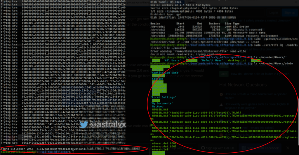
Dislocker is an open-source Linux driver to read Bitlocker encrypted partitions, it supports decryption using VMK. Throw every 32-byte commination in your stream at this Dislocker tool, and after a few 1000 attempts a key will finally succeed.
Mount the decrypted Dislocker NTFS file with the use of ntfs-3g and vo’ila. Fig 8 shows the decrypted and mounted contents of a Bitlocker encrypted drive plugged into a separate Linux machine.
Mitigations
Enable key protectors such as alphanumeric PIN or startup key on USB, so an attacker needs to have this additional information if the SSD is stolen; TPM has anti-hammering capabilities to prevent brute forcing these. Instead of discrete TPM use a Firmware TPM (fTPM) such as provided by AMD PSP, this has a TPM IP Block in the SOC itself, thus uses internal chip communication and no use of public SPI bus. Have Microsoft enable TPM parameter encryption from Bitlocker in preboot to encrypt the commands and responses using an authsession.
References
[1] Bitlocker FIPS 140-2 https://csrc.nist.gov/csrc/media/projects/cryptographic-module-validation-program/documents/security-policies/140sp947.pdf
[2] Infineon Xenon TPM specs https://www.infineon.com/dgdl/Infineon-Xenon_4-0-2_9670_HD-AdditionalTechnicalInformation-v01_01-EN.pdf?fileId=5546d46271bf4f920171ef849cdc5678