This is the circuit diagram we will create. Video below.
7-segment display
Each segment is an LED, and collectively they can represent all single numerical digits. For convenience each segment is assigned a letter from a to g.
E.g. to display the digit ‘1’, we would enable segment b and c.

Truth table
To represent digits 0-9, encoded in binary, we need 4 bits, 0b0000 – 0b1001. However for simplicities sake further down relating to length of equations we will stick to 3 bits which will represent 2^3=8 outputs (0b000 – 0b111, or 0 – 7). As previously described to display the digit 1 (0b001), we need to enable segment b and c. In the following truth table A = lowest significant bit (LSb), and D = most significant bit (MSb), we see all the necessary segment to display all digit outputs.
| DIGIT | BCD INPUTS | 7-SEGMENT OUTPUTS | ||||||||
| C | B | A | a | b | c | d | e | f | g | |
| 0 | 0 | 0 | 0 | 1 | 1 | 1 | 1 | 1 | 1 | 0 |
| 1 | 0 | 0 | 1 | 0 | 1 | 1 | 0 | 0 | 0 | 0 |
| 2 | 0 | 1 | 0 | 1 | 1 | 0 | 1 | 1 | 0 | 1 |
| 3 | 0 | 1 | 1 | 1 | 1 | 1 | 1 | 0 | 0 | 1 |
| 4 | 1 | 0 | 0 | 0 | 1 | 1 | 0 | 0 | 1 | 1 |
| 5 | 1 | 0 | 1 | 1 | 0 | 1 | 1 | 0 | 1 | 1 |
| 6 | 1 | 1 | 0 | 1 | 0 | 1 | 1 | 1 | 1 | 1 |
| 7 | 1 | 1 | 1 | 1 | 1 | 1 | 0 | 0 | 0 | 0 |
Boolean expressions
Now convert each segment to a boolean expression. Where an input sequence generates an output of 1 for segment a, write out the expression where any input of 0 has a not symbol (e.g. Ā or A’), if an input has 1 then it’s (e.g. A) .
I.e. a=1 when Digit==2, CBA==010, thus expression of inputs = C’ ⋅ B ⋅ A’
| DIGIT | BCD INPUT | 7 SEG OUTPUT | BOOL EXPRESSION | ||
| C | B | A | a | ||
| 0 | 0 | 0 | 0 | 1 | C'B'A' |
| 1 | 0 | 0 | 1 | 0 | |
| 2 | 0 | 1 | 0 | 1 | C'BA' |
| 3 | 0 | 1 | 1 | 1 | C'BA |
| 4 | 1 | 0 | 0 | 0 | |
| 5 | 1 | 0 | 1 | 1 | CB'A |
| 6 | 1 | 1 | 0 | 1 | CBA' |
| 7 | 1 | 1 | 1 | 1 | CBA |
Now use the sum of products rule and accumulate all the boolean expressions where the segment a = 1. Resulting in:
a = C’B’A’ + C’BA’ + C’BA + CB’A + CBA’ + CBA
Decoder minimization using Karnaugh maps
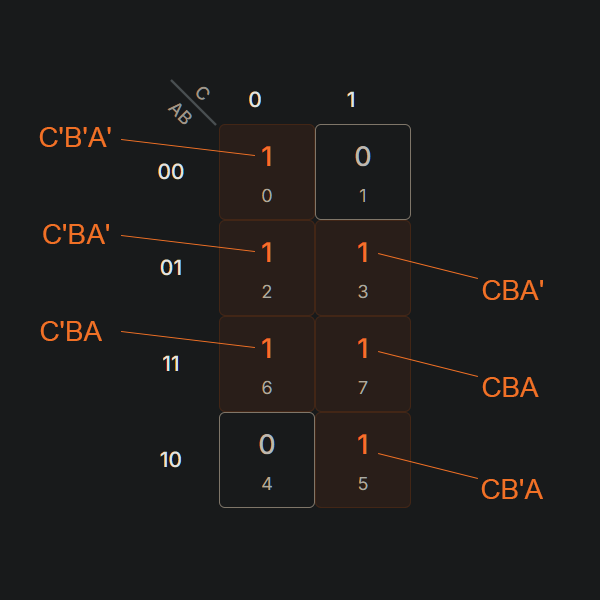
The above boolean expression is unoptimized and will require more gates than necessary. We can use a Karnaugh map to simplify the boolean expressions. With our 3-inputs, we will create a 3×3 matrix. Since order does not matter in multiplication, choose 2 inputs for the top row, and 1 inputs for the left column. E.g. AB and C. Then using the above sum of product result, fill in a 1 in any of the AND expressions.
Now apply the Karnaugh Map Rules, by combining cells containing a 1 to make groups of cells.
- Groups should contain as many ‘1’ cells as possible, with no ‘0’ cells
- Groups can only be sized in powers of 2 e.g. a square of 1, 2, 4, 8, etc
- A ‘1’ cell can be grouped with adjacent ‘1’ cells that are immediately above, below, left, right of the cell. No diagonal grouping
- Groups of ‘1’ cells can overlap
- The top/button and left/right edges of the map are considered continuous, and larger groups can be considered by crossing the edges
- There should be as few groups as possible

Now we can visually simplify the expression. Find all terms that do NOT change in a group and that is the simplified expressions.
E.g. for the orange above, C=0 does not change for both cells, A=0 does not change either, notice B changes from 0 to 1 between cells. Thus the simplified expression for the orange group is A’C’.
- Orange = A’C’
- Green = B
- Purple = AC
Thus for segment a, the simplified boolean expression is:
a = A’C’ + B + AC

Repeat this for all segments from a to g, gives us:
- a = B + AC + A’C’
- b = C’ + A’B’ + AB
- c = C + B’ + A
- d = BC’ + A’C’ + A’B + AB’C
- e = A’C’ + A’B
- f = B’C + A’B’ + A’C
- g = B’C + A’B + BC’
Asynchronous counter
To get our digits from 0 – 7, create a counter of 3 bits. Using 3 D flip-flops, each output Q’ feeds back into its input D. The first flip-flop CK is fed in from the desired clock, all other flip-flops use the previous flip-flops Q’ as the CK. Where as Q output is a bit of the BCD.
N.b. Q0 here is the LSb, and Q2 is the MSb.

Finale
Combing this all together, we arrive at this circuit. Notice digit 1 required segment b and c. Based on async counter at the top with 3x flip-flops, it has activated the b and c expressions.
Apologies for not perfecting all the wiring. To see it in action run the video at the top of the page.
To run it yourself in your browser, use the link below. Hit the green play button, then click the switch next to the 1Hz clock to start the clock, optionally press the reset button to reset all the flip-flops: https://wokwi.com/projects/446363784753530881
